Commercial Push Pier Systems in Charleston, Charlotte, Columbia & all South Carolina
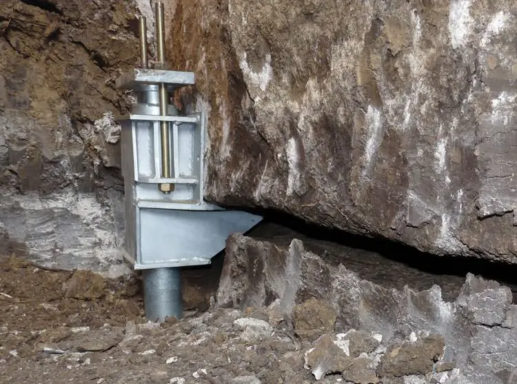
The Supportworks push pier system utilizes high-strength round steel tubes and a load transfer bracket (retrofit foundation repair bracket) to stabilize and/or lift sinking or settling foundations.
Financing Available
Foundation Underpinning in SC, NC, AL & GA
Foundation Inspection & Diagnosis
Push Pier System Installation
Sinking Foundation & Wall Repair
Uneven Floor and Door Solutions
what Are Push Piers?
Push piers are heavy-duty steel piers hydraulically driven into the ground through unstable soil until they reach bedrock or a load-bearing stratum. Once in place, they are attached to the foundation with a secure bracket, allowing the structure’s weight to be transferred to more stable ground.
Push piers are ideal for commercial buildings showing signs of foundation settlement, and they can often restore the structure to its original position.

Supportworks Pier System Specifications
Model 288 Pier System Specifications
Model 288 Pier System Specifications
Bracket: Weldment manufactured from 0.25″, 0.375″, and 0.50″-thick steel plate. Yield strength = 36 ksi (min.), tensile strength = 58 ksi (min.).
External Sleeve: 3.50″ OD x 0.216″ wall x 30″ or 48″ long with sleeve collar welded to one end. Yield strength = 50 ksi (min.), tensile strength = 62 ksi (min.).
Pier Starter Tube: 2.875″ OD x 0.165″ wall x 50″ long, triple-coated in-line galvanized. Yield strength = 50 ksi (min.), tensile strength = 55 ksi (min.). 3.375″ OD x 0.188″ wall x 1″ long friction reducing collar welded to one end.
Pier Tube: 2.875″ OD x 0.165″ wall x 36″ long, triple-coated in-line galvanized. Yield strength = 50 ksi (min.), tensile strength = 55 ksi (min.). 2.50″ OD x 0.180″ wall x 6″ long internal coupler at one end with 3″ extending out of pier tube.
Pier Cap: 5.0″ wide x 9.0″ long x 1″ thick plate with confining ring welded to one side. Yield strength = 50 ksi (min.), tensile strength = 65 ksi (min.).
All-Thread Rod: 0.75″ diameter x 16″ long, zinc plated, Grade B7, tensile strength = 125 ksi [min.].
Model 350 Pier System Specifications
Model 350 Pier System Specifications
Bracket: Weldment manufactured from 0.38″, 0.50″, and 0.63″ thick steel plate, Yield strength = 36 ksi (min.), tensile strength = 58 ksi (min.).
External Sleeve: Ø4.000″ x 0.226″ wall x 48″ long with sleeve collar welded to one end. Yield strength = 50 ksi (min.), tensile strength = 62 ksi (min.).
Pier Starter Tube: Ø3.500″ x 0.165″ wall x 50″ long, triple-coated in-line galvanized. Yield strength = 50 ksi (min.), tensile strength = 55 ksi (min.). Ø4.000″ x 0.226″ wall x 1″ long friction reducing collar welded to one end.
Pier Tube: Ø3.500″ x 0.165″ wall x 36″ long, triple-coated in-line galvanized. Yield strength = 50 ksi (min.), tensile strength = 55 ksi (min.). Ø3.125″ x 0.180″ wall x 6″ long internal coupler at one end with 3″ extending out of pier tube.
Pier Cap: 4.00″ wide x 8.50″ long x 1.25″ thick plate with pier locator plate welded to one side. Yield strength = 50 ksi (min.), tensile strength = 65 ksi (min.).
All-Thread Rod: Ø7/8″ x 18″ long, zinc plated. Grade B7, tensile strength = 125 ksi (min.).
Model 400 Pier System Specifications
Model 400 Pier System Specifications
Bracket: Weldment manufactured from steel plates with integrated pipe sleeve. Steel plate: 0.38″ and 0.50″ thick steel plate, yield strength = 36 ksi (min.), tensile strength = 58 ksi (min.). Pipe sleeve: Ø4.50″ x 0.237″ wall x 14.50″ long. ASTM A53 Grade B Type E & S, yield strength = 35 ksi (min.), tensile strength = 60 ksi (min.).
Pier Starter Tube: Ø4.00″ x 0.226″ wall x 36″ long. ASTM A500 Grade B or C, yield strength = 50 ksi (min.), tensile strength = 62 ksi (min.). Ø4.50″ x 0.237″ wall x 1″ long friction reducing collar welded to one end.
Pier Tube: Ø4.00″ x 0.226″ wall x 36″ long. ASTM A500 Grade B or C, yield strength = 50 ksi (min.), tensile strength = 62 ksi (min.). Ø3.50″ x 0.216″ wall x 8″ long internal coupler at one end with 4″ extending out of pier tube.
Pier Cap: 4.00″ wide x 8.50″ long x 1.25″ thick plate with pier locator plate welded to one side. ASTM A572 Grade 50, yield strength = 50 ksi (min.), tensile strength = 65 ksi (min.). All-Thread Rod: Ø0.875″ x 18″ long, zinc plated. ASTM A193 Grade B7, tensile strength = 125 ksi (min.).
Push Pier System Considerations
Design Considerations
Friction Reducing Collar
ready to fix it? LET'S GET STARTED
Commercial PUSH PIER PROCESS
Free Inspection & Assessment
Every project begins with a detailed inspection of the foundation and surrounding structure. We look for cracks, separation, settlement patterns, and other signs of movement to determine the extent of the issue. Soil conditions and structural load are also considered to confirm that push piers are the right solution. Based on this evaluation, we determine the number of piers needed and their exact placement to properly support the structure.
01
Site Preparation
Small excavations are made next to the foundation footing at each planned pier location. These access points allow our crew to reach the footing without unnecessary disruption to landscaping or hardscaping. The excavation is sized only as large as needed to install the bracket and drive the pier. Care is taken to protect the surrounding area throughout the process.
Pier Driving
Galvanized steel push piers are hydraulically driven into the ground using the weight of the structure. Each pier section is advanced until it reaches stable, load-bearing soil or bedrock. The driving process continues until the required resistance is achieved, confirming the pier has reached competent strata. This ensures the load will be transferred to soil that can properly support the structure.
Bracket Attachment
Once the pier reaches suitable depth, a heavy-duty steel bracket is secured to the foundation footing. This bracket connects the structure directly to the pier shaft below. The connection allows the building’s weight to shift from unstable soil to the deeper load-bearing layer. All components are tightened and aligned to ensure long-term performance.
Controlled Lift (If Applicable)
If conditions allow, the structure can be carefully lifted to improve levelness. Hydraulic equipment applies controlled pressure across the installed piers to raise settled areas. This process may help close cracks, realign doors and windows, and reduce visible separation. Elevation is monitored throughout to maintain uniform support
Backfill & Restoration
After installation and lifting are complete, the excavated areas are backfilled and compacted. Soil is restored to proper grade to prevent drainage issues. Disturbed landscaping or surface areas are cleaned and returned to their original appearance as much as possible. The goal is to leave the property stable, supported, and looking well maintained.
Why Choose Cantey for Commercial Push Piers?
Commercial Experience That Matters
We have experience working in light industrial, retail, warehouse, municipal, and hospitality environments. Our team understands the operational demands of commercial properties and delivers concrete leveling solutions that align with safety standards and business schedules.
Minimal Disruption to Operations
Many push pier installations are completed efficiently with minimal disruption to the property. Our team works methodically to stabilize the foundation while limiting impact to the structure and surrounding areas, helping you address settlement without unnecessary delays or extended project timelines.
Proven Performance in Soils
Our pier systems have proven performance in South Carolina, North Carolina, and Georgia soils. That experience matters because soil behavior drives settlement, and the solution has to match local ground conditions to deliver long-term stability.
25-Year Transferable Warranty Coverage
All pier systems come with a 25-year transferable warranty. That warranty provides long-term protection for your investment and can be a meaningful benefit if you sell the property, since coverage can transfer to the next owner.
Minimal Impact to Landscaping and Hardscaping
Our approach is designed to minimize invasion to landscaping or hardscaping. We plan access and installation methods to reduce disruption around the home, helping protect features like plantings, walkways, and exterior surfaces whenever possible.
Honest Assessments and Custom Solutions
You get an honest assessment based on what your foundation actually needs. We provide custom solutions rather than a one-size-fits-all approach, so the plan fits the structure, site conditions, and the specific issues causing movement.
Benefits of Our Push Pier Systems
Permanently stops foundation settlement
Transfers weight to stable, load-bearing soil
Allows for possible lift of the home to original position
Installed year-round in most weather conditions
Fast installation—typically 1–3 days
Ideal for heavy structures with deep settlement
Requires minimal surface disruption
Engineered to perform in weak or expansive soils
Backed by a 25-year transferable warranty
Our Customers Say it Best
How are push piers different from helical piers?
Will the repair stop further settlement?
How much exterior disturbance is there?
How do you know how many push piers are needed?
The number of push piers is determined during the inspection process. We evaluate the structure, settlement patterns, and load-bearing points to design a stabilization plan that places piers where they will provide the most effective long-term support.
Is there a warranty?
frequently asked questions about commercial push piers
Get a free inspection of your foundation
Get a clear diagnosis and a permanent solution for your commercial property.